Wiring and Circuits
SMART Demographics Questionnaire
Introduction
Simplest Circuit
Quiz: Simplest Circuit
Conductors and Insulators
Mini-Challenge: An Unwanted Shortcut
Quiz: Conductors & Insulators
Wires
Quiz: Wires
Connectors
Mini-Project: Test Your Wire
Mini-Project: Electrical Tape
Quiz: Connectors
Simple Switches
Other Types of Switches
Unit Project: Lightbox
Back to Overview
Introduction
It is important for a circuit to be electrically connected in the right places (to form a closed circuit), but also NOT be connected in the wrong places (no short circuits). Therefore, most electrical systems are connected using wires. A wire is a conductor wrapped in an insulator.
The conductor on the inside forms an electrical connection, while the insulator keeps undesired objects from making an electrical connection to the circuit. A small portion of the conductor is usually exposed at the ends, so they can be connected to the rest of the circuit.

Required items and tools
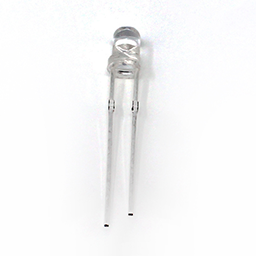
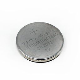
Find the following components:


Mini-Challenge: Styrofoam-core Posterboard
Create the following board using a piece of cardboard or styrofoam-core posterboard.

Instructions:
- Attach your LED and coin cell battery to the board where indicated.
- Use wires to electrically connect the LED and coin cell so the LED lights up. It's okay if your setup isn't very stable for now.
Hints:
- You will need two wires.
- Connect the + side of the battery to the long leg of the LED, and the - side of the battery to short leg of the LED.
- Make sure the metal conductor parts of the wires touch the metal legs (on the LED) and the metal surfaces on the battery.
Did You Know? Schematics
In the world of electrical engineering and design, communicating circuit designs is a crucial aspect. One common method used is schematics, a symbolic representation of circuits. A simple illustration of a circuit, such as a coin cell battery connected to an LED, can be represented both as a physical layout and as a schematic diagram.

Schematics use standardized symbols to represent various components and connections in a circuit, making it easier for engineers and technicians to understand the design, regardless of language or specific training in a particular type of circuitry. This universal language of symbols in schematics provides a clear, concise, and efficient way to convey complex electrical information.
Diagram and Schematic Print-Out