Before using any tools, be sure to use appropriate eye protection, hearing protection, and safety precautions. If you are participating in a course, ask the instructor for any tips on the safe handling of tools if needed.
Introduction
In this lesson, you will cut a small, blank piece of aluminum from a larger aluminum plate to design a draft piece of a motor mount. Throughout this unit, you will practice the skills needed to make a motor mount on this draft piece. Ultimately, you be able to make a final motor mount in the unit project.
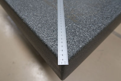
If not available, any hard flat surface should work
Step 1: Acquire Aluminum
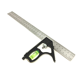
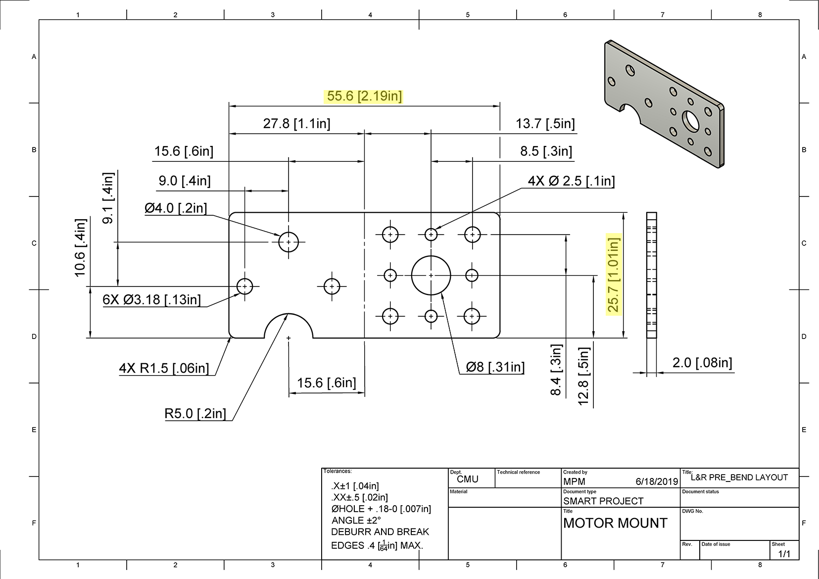
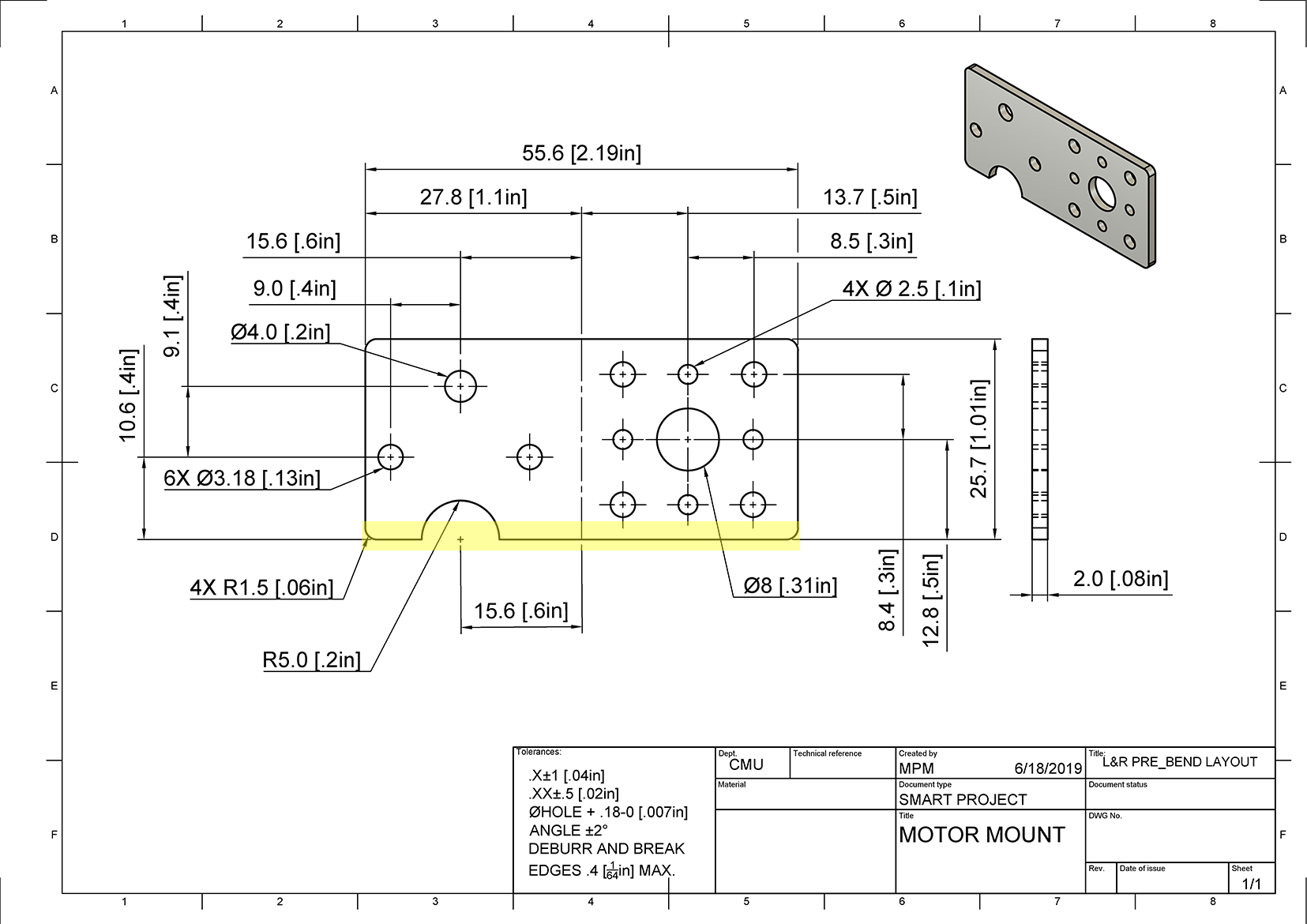
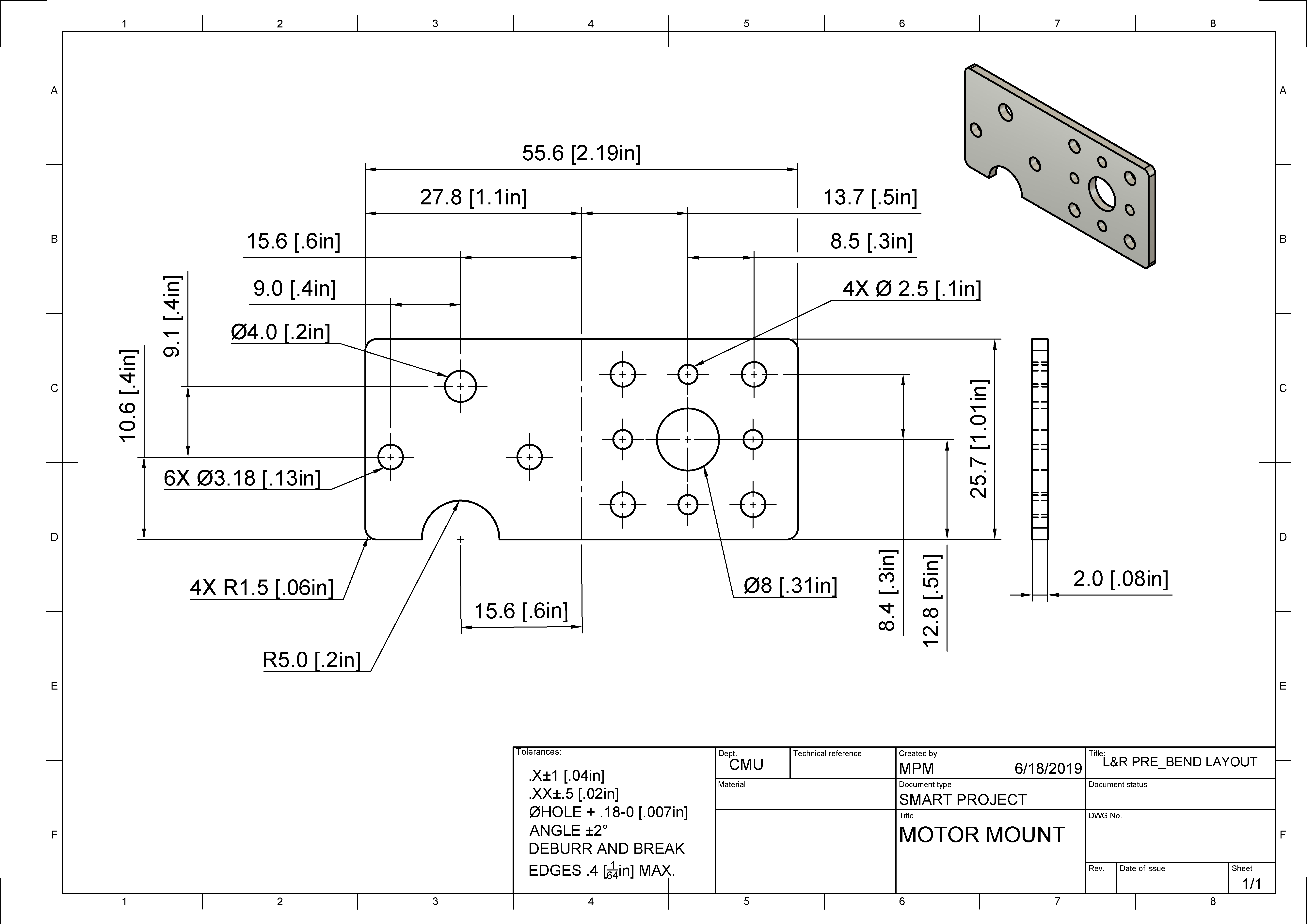
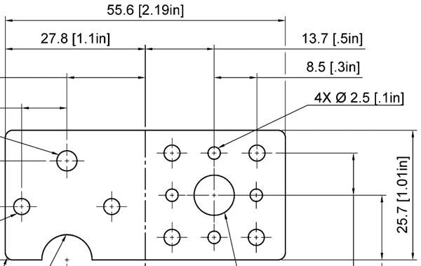
Acquire a piece of aluminum material. Make sure that the material is big enough to cut the piece in the drawing below by using a Combination Square to measure its length and width. The highlighted values in the drawing below represent the desired length and width of your practice motor mount.
Align the 90-degree edge portion of the Combination Square to an edge of the sheet of aluminum material to check that it is completely straight. This will be your "datum A" line. This means that this side acts as a reference point. Datum A is a line to which dimensions are referred on technical drawings as a standard of comparison.
Motor Mount Datum
Note: The drawing above shows the Datum A line on the already cut motor mount. You are to identify the same Datum A line on the sheet of aluminum material. This will give you a sense on where you are cutting.
Step 3: Scribe Lines
To prepare the piece for cutting, you will scribe lines that show the shape of your practice motor mount. The drawings below give exact dimensions and placement of where you should scribe your lines. It may help to trace the scribed lines in marker to see them better when you cut.
You will need to create two sides for the motor mount. Luckily, one of those should be a factory edge of the aluminum. Using the Combination Square and Scriber, scribe the other side that is perpendicular (a side that is at a 90-degree angle) from “datum A” using the dimensions on the drawing.
Motor Mount Side Line
Using the Combination Square, scribe a fourth line that is parallel to datum A using the dimensions as shown in the drawing. Motor Mount Forth Line
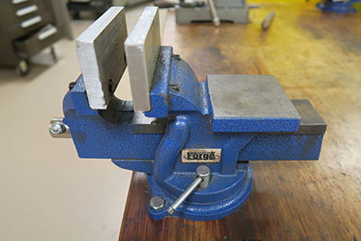
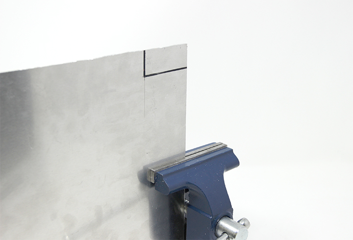
Step 4: Place Material in a Bench Vise
Place the aluminum material into the Bench Vise and tighten the Bench Vise until the material stays in place.
Material in Bench Vise
Note: Do not overtighten! It will leave marks on the material. Tighten just enough to keep the material in place without it moving while sawing.
Step 5: Saw Scribed Lines
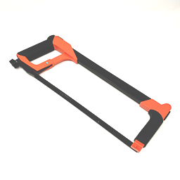
Place the aluminum on the Granite plate or flat surface. Using the Hack Saw, cut the scribed lines. Be sure to stay as straight as possible.
Hacksaw cutting the aluminum material
Tip: Do not put use much force while cutting! Take it slow, and smooth motions.
Step 6: File the Edges
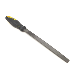
Using the Hand File, file the edge of the material to remove any rough surfaces.
File the edges
Step 7: Check Tolerance
Using the Combination Square, check that the dimensions fit within the acceptable range or, tolerance. Tolerance is a value that tells you how much room for error is allowed. It gives a range of values that represent how much bigger or smaller an object can be from the original dimension. In other words, an object does not always have to be exact to the desired dimensions as long as the object's dimensions are within the acceptable range.
The acceptable range is calculated using the tolerances listed in the Tolerance Block located on the bottom of the drawing. On a part, different measurements can have different tolerances depending on how precise that measurement is. For example, a measurement of 200.00 mm is more precise than a measurement of 200.0 mm. The precision and the number of decimals a measurement has also determine what tolerance that measurement has.
If your material is slightly out of the tolerance range, it's okay! Remember that this is a practice piece and it's okay to make a mistake.
Calculate the tolerance
Explanation
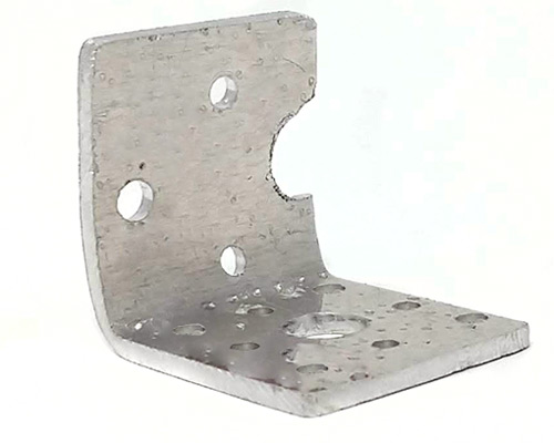
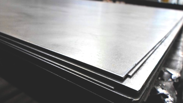
You should now have a piece of aluminum that you will use to practice drilling, cutting, and bending before making your motor mount! Working with aluminum is a bit different than working with polycarbonate. The type of aluminum you will be using throughout this lesson is called 3003-H14 aluminum. The 3003 part of it refers to the grade of the aluminum (and how much of other metals are mixed with it - giving it its unique characteristics). Some examples of characteristics of aluminum grades are strength, its ability to be cut (aka machined), corrosion resistance, and if it can be heat treated (heat treatability). Other examples are 1000, 3000, 4000, all the way to 8000 grades (referred to as series).
Aluminum Plates
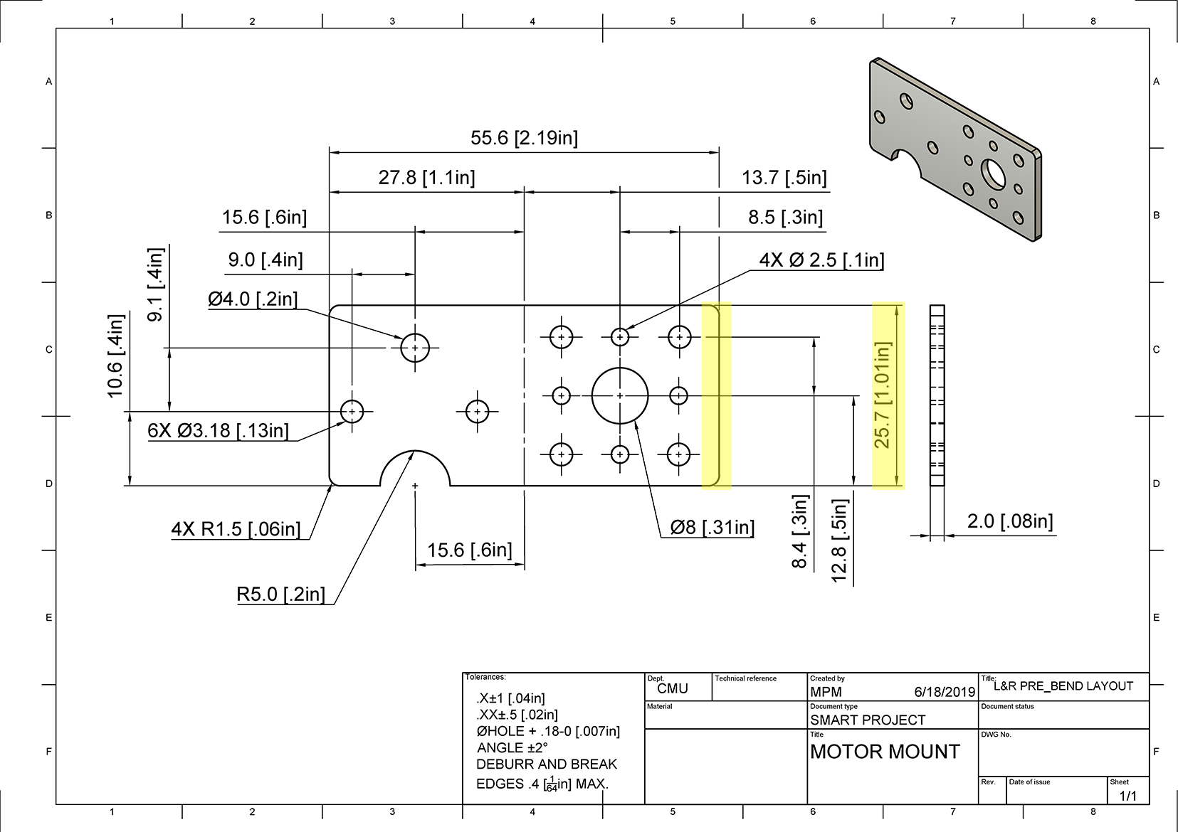
Based on the following drawing, how tall is the piece of metal for the motor mount?
Drawing
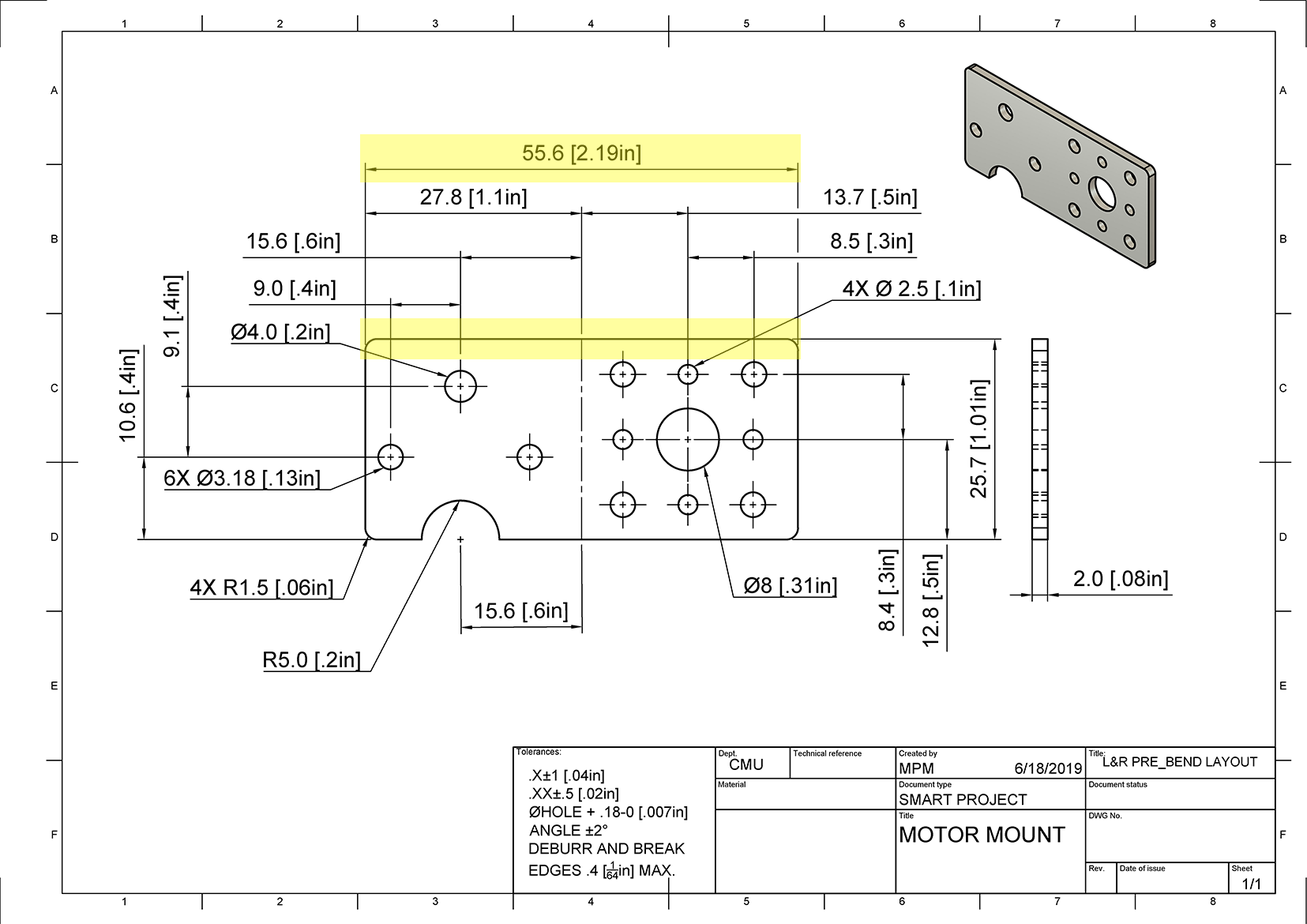
Based on the following drawing, how wide is the piece of metal for the motor mount?
Drawing
What does it mean for a line to be perpendicular from Datum A?
True or False. Safety equipment is not important when carefully cutting aluminum.